PROJECT 11 / January 2026
Aluminum base plate manufacturing
Layout, drilling, chamfering, and tapping
Michigan State University
How does careful layout carry through to usable threaded mounting features?
My contribution
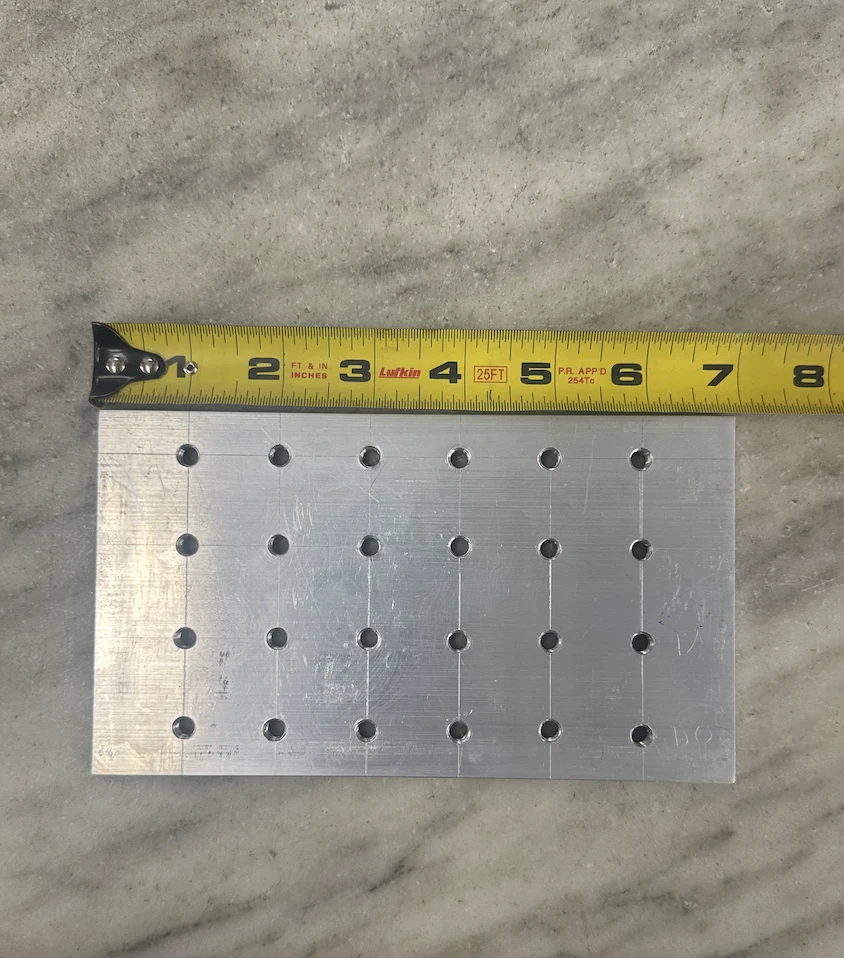
The base plate started as aluminum stock measuring 0.25 × 4 × 7.125 inches. Its drawing specified a grid of 24 threaded holes for mounting components in a slider crank assembly.
I contributed to layout, center punching, drilling, chamfering, hand tapping, and inspection as part of a four person team. We used layout fluid, a surface plate, and a height gauge to mark the hole locations before drilling. We chamfered the openings on both sides and cut 1/4 inch, 20 threads per inch internal threads with cutting fluid.
Our team completed the assigned portion of the hole pattern; the photographed plate includes the full grid. We checked dimensions with calipers and tested bolt engagement. The report documented small positioning deviations that did not prevent the threaded features from functioning. The bolts engaged smoothly.
This work gave me practical experience translating a drawing into a sequence of shop operations and checking how layout accuracy carries through drilling and tapping.
Completed usable threaded features with smooth bolt engagement and documented inspection.
The process
- 01
Lay out and center punch the hole locations
- 02
Drill, chamfer, and tap the assigned features
- 03
Check dimensions and bolt engagement
Source: Team manufacturing report and inspection photographs supplied by Daniela Ojeda.